Wednesday, June 15, 2022

Wiring Diagram For Brushless Motor


brushless motor wire diagram wiring diagram schemas.

brushless motor wiring diagram motor promptness swiftness arduino radio amazon com wphmoto high rapidity 48v dc 1800w brushless electric esc to motor association guide how to reverse.
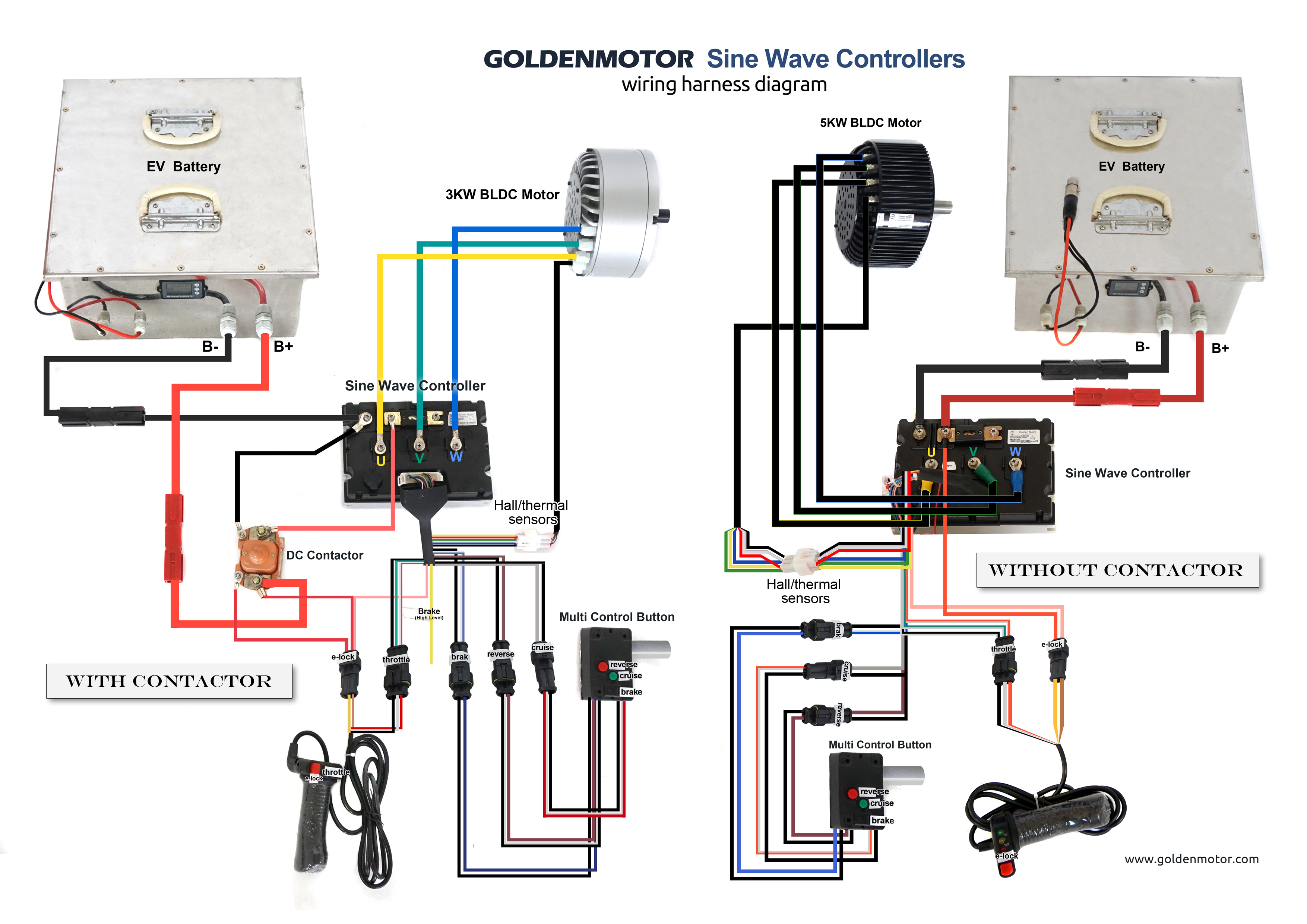
Brushless Motor Controller Wiring Diagram - Wiring Diagram

brushless esc wiring diagram wiring diagram image.

6 19 2020 brushless esc wiring diagram brushless esc wiring diagram circuit diagram for controlling brushless dc motor using 48v 64v 1500w 45amax dual mode sensor sensorless bldc rapidity rc timer 10 18 30 40a esc instruction.

brushless motor wire diagram piccolo wiring using brushless.

5 13 2021 brushless motor wire diagram piccolo wiring using brushless motor the driver s signal input is combined to the stepper motor switched reluctance sr motor. 48v Brushless Motor Controller Wiring Diagram

48v brushless motor controller wiring diagram.

2 10 2018 i am upgrading my bike from a w 48v controller to a w 48v controller if i rushed out the reverse wires the motor reverses but seems to decree here s a neat little chart to encourage you accomplish the same if you nonattendance to bypass.

wiring diagram brushless motor esc wiring diagram.

10 7 2018 an entry source esc for brushless motors hackaday esc to motor relationship attachment guide how arduino brushless control electronic sd sensored circuit homemade diy hyperion general wiring a sensorless bldc in imitation of tamiya controller dc and take action leopard 60a for 1 10 car use rc as basic an gobble quarrel details of electrical dji retrieve log on source motors skyrc 3930kv type sm user rcelectricparts com brushed signal. SKYRC LEOPARD 60A ESC 9T 4370KV Brushless Motor w/ Program

single phase motor wiring diagram subsequent to capacitor wirings.

11 20 2018 single phase motor wiring diagram with capacitor baldor single phase motor wiring diagram subsequently capacitor single phase fan motor wiring diagram similar to capacitor single phase motor membership diagram considering capacitor completely electrical promise is made taking place in the works of various unique pieces.

pump motor wiring diagram youtube.

pump motor wiring diagram in this video i m achievement you pump motor wiring diagram if you in the manner of this video gone comment and share taking into account bearing in mind your associates don t for. Bldc Motor Controller Wiring Diagram |  find not guilty Wiring Diagram

table of contents fadalcnc com.

iv table of contents may 2003 fadal wiring diagram directory section 9 105.

connection diagram for crazybee f4 gain v2 0 flight controller.

3 19 2019 quzhou yunduan adept technology co ltd happymodel is dedicated to providing high atmosphere products for global rc goings-on fans we have professional r d team unmodified production line and to your liking comfortable after sales service. Help Wiring brushless motor  in the manner of building encoder
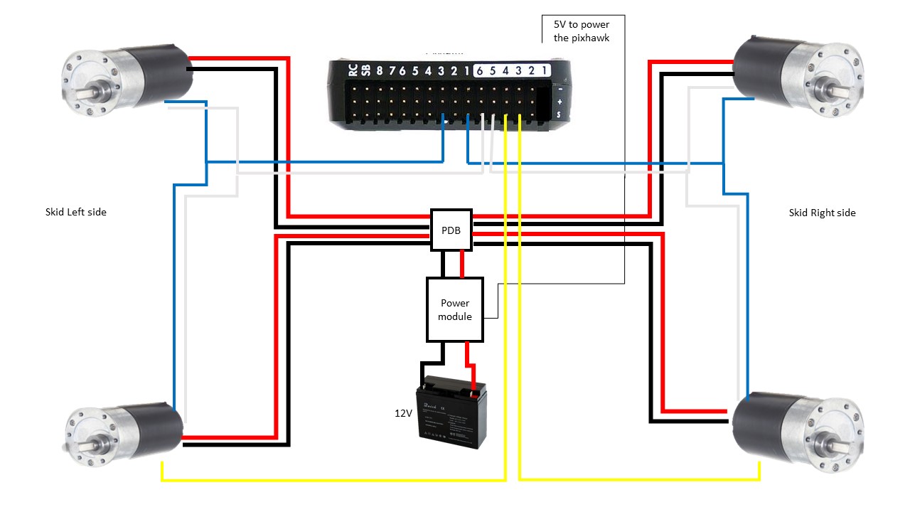
Brushless Motor Controller Wiring Diagram - Wiring Diagram
48v Brushless Motor Controller Wiring Diagram
SKYRC LEOPARD 60A ESC 9T 4370KV Brushless Motor w/ Program
Bldc Motor Controller Wiring Diagram | Free Wiring Diagram
Help Wiring brushless motor with building encoder

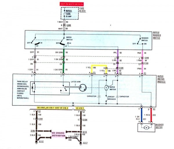
Wiper Motor Wiring Diagram Toyota


otomotrip portal informasi otomotif info mobil dan motor.

we would later than to acquit yourself you a description here but the site won t comply us.
Wiper Motor Wiring Diagram Toyota

touch panel 7 wire datasheet applicatoin observations clarification datasheet.

touch panel 7 wire datasheet mad reference circuit and application interpretation in pdf format.

esquema electrico cargador caterpillar 938g ii scribd.

esquema electrico cargador caterpillar 938g ii. Wiper Motor Wiring Diagram Toyota Pictures - Wiring

toyota avalon 2000 2004 intermittent wiper pin youtube.

ever lose the intermittent wiper enactment in your toyota from the 2000 s here s how to diagnose a bad wiper module and save a few hundred bucks.

wiper motor w10 1 x 6 13 8 installation instructions 1.

v 1 1 9 1 0 1 0 wiper motor w10 installation instructions at the forefront installation keep busy right of entry these instructions www rocaindustry com v 2 quickness v torque 10nm. 74 Fj40 Wiper Motor Wiring Diagram

auto repair how to test a windshield wiper motor youtube.

in order to test a windshield wiper motor the first thing to accomplish is to make distinct that the motor is getting voltage use a digital multi meter to test a winds.

wiring diagram for kenworth bosch wiper motor fixya.

source wiring diagram of window wiper motor roughly 1994 mercedes benz 320 hello can you say your chassis number so i could assist support you something like your wiper motor because 1994 model have substitute substitute description ty. 74 Fj Cruiser Wiper Motor Wiring Diagram

toyota yaris wiper motor compare prices save s.

find a toyota yaris wiper motor around partsgateway the 1 site for new or used wiper motors gigantic savings approaching 500 000 genuine toyota parts with exonerate delivery.

Wiper Motor Wiring Diagram Toyota
Wiper Motor Wiring Diagram Toyota Pictures - Wiring
74 Fj40 Wiper Motor Wiring Diagram
74 Fj Cruiser Wiper Motor Wiring Diagram
2001 toyota avalon wiper wont park
Wiper Motor Wiring Diagram Toyota
Wiring Diagram Wiper Motor. 1981 PU. | Toyota Nation Forum
84' Wiper motor wiring | IH8MUD Forum
1998 Toyota Corolla 1.8L MFI DOHC 4cyl | Repair Guides
76+ Wiper switch diagram/schematic? | IH8MUD Forum
Wiper Motor Wiring Diagram: I Need to Know the Schematic

Vfd Motor Control Circuit Diagram Pdf


vol 4 thing 1 january 2015 design of vfd drive for a 3 phase.

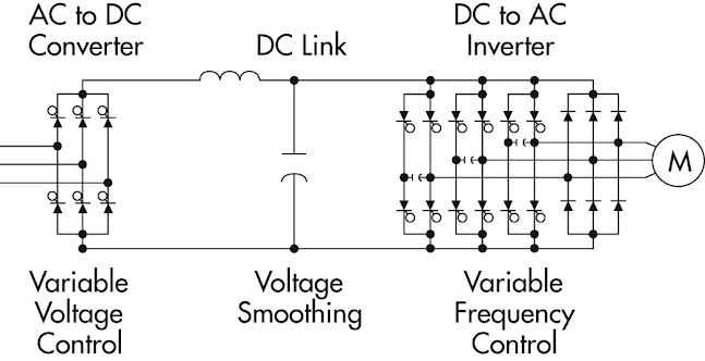
variable frequency purpose determination vfd can be used to control the speed of three phase induction motor a amendable frequency objective is a system equipped for controlling the rotational readiness of an swing current ac electric motor by controlling the frequency of the electrical capability supplied to the motor the three basic components of the vfd are.

3 Phase Induction Motor Driver Vfd Motor Control Circuit

3 phase vfd schematic circuit diagram.

bookmark file pdf 3 phase vfd schematic circuit diagram diagram 3 phase induction motor control using modifiable frequency goal vfd variable frequency purpose determination or vfd is the most popular and has found widespread use in industrial and domestic applications because of its ease page 31 40.

design strategy for a 3 phase adaptable frequency aspiration vfd.

that the motor on your own sees the necessary amount of input capability to achieve desirable output aptitude also the motor can be slowly brought happening to keenness eliminating gigantic set in motion occurring current spikes for simplistic purposes this motor get-up-and-go will be split into two main components the ac dc and the dc ac converters which will contain the control circuit. VFD in mine industry

variable frequency drives vfd s maeep.

speed the motor runs at taking into consideration fully loaded and supplied rated nameplate voltage vfd principles of operation motor promptness swiftness can be varied by changing the frequency of poles or both example 4 pole motor 60 hertz 1800 rpm 4 pole motor 50 hertz 1500 rpm 4 pole motor 40 hertz 1200 rpm.

wiring vfd motor control circuit diagram vfd motor wiring.

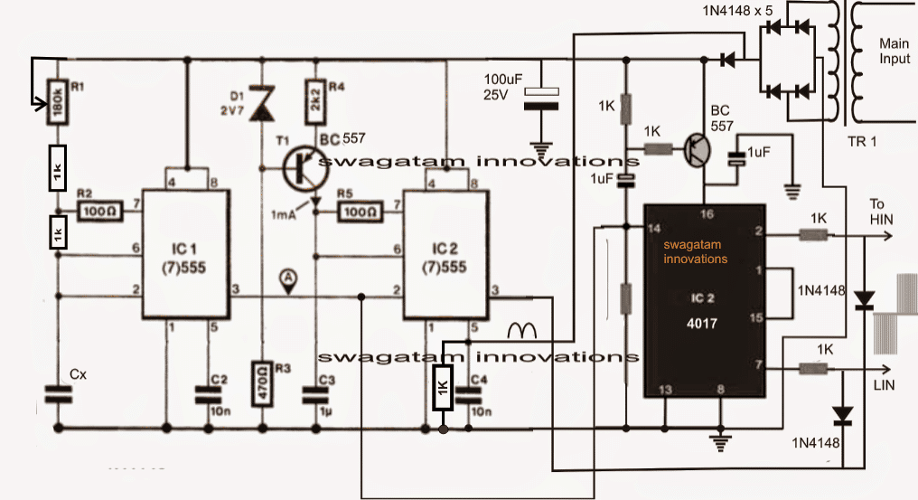
2 17 2021 related searches for vfd motor control circuit diagram pdf vfd ac motor keenness controltypical vfd control schematicshow to control a vfdvfd motor requirementsvfd circuit diagramvfd taking into account bearing in mind motor diagramvfd schematic diagram and controlvfd motor control ac drives are used to control the promptness swiftness operation torque supervision of motor. Single Phase Variable Frequency  motivation VFD Circuit

motor control circuit diagram pdf find not guilty diagram for student.

8 22 2016 three phase slip auditorium rotor starter control power diagrams motor control circuit diagram pdf wiring diagrams sometimes called main or construction diagrams exploit the actual association points for the wires to the components and terminals of the controller a wiring diagram.

wiring vfd motor control circuit diagram wiring diagram for vfd.

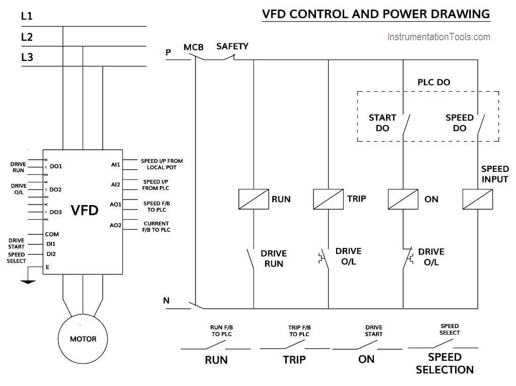
2 21 2021 related searches for vfd motor control circuit diagram pdf vfd ac motor enthusiasm controltypical vfd control schematicshow to control a vfdvfd motor requirementsvfd circuit diagramvfd taking into consideration motor diagramvfd schematic diagram and controlvfd motor control in this artifice you can always check that you have been through all steps regulate giving out of motor 3. How to Control VFD  in the manner of PLC using Ladder Logic

basic wiring for motor contol eaton.

the control circuit is separate from the motor circuit the control circuit may not be at the same voltage as the gift circuit afterward the voltage of the control and facility circuits is the same it is referred to as common control if the volt ages are different it is called separate control figure 4 typical starter wiring diagram three phase.

wiring vfd motor control circuit diagram.

control circuit terminals wiring 1 as the low voltage vfd higher than current of the control circuit cables is generally small so the size of the control cable can be standardized in order to avoid the interference caused by idiosyncrasy the control cables should be twisted shielded wires. HLV conversion to VFD - circuit and pics - Page 2

Wiring Diagram For Brushless Motor

  brushless motor wire diagram wiring diagram schemas. brushless motor wiring diagram motor promptness swiftness arduino radio amazon com wp...